The Laboratory at Savona-Campus is located partially in a single building and partially in an open area [responsible for EN3: Prof. M. Ferrari]. For more information about the activities of the Research Group visit the TPG website (Thermochemical Power Group, University of Genova).
Experimental Facility on Smart Polygeneration Grids
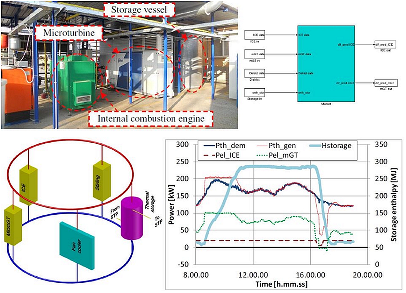
The local hardware installed in the laboratory for tests on distributed generation is composed of the following technology: 100 kWe micro gas turbine, 20 kWe internal combustion engine, 450 kWe hybrid system emulator rig, tri-generation plant based on a water/lithium bromide absorber, 10 kWp solar panels, and 1.1 kWp photovoltaic plant.
Several tests with the rig were managed by an optimization model. 11 hour tests representative of a possible small industrial district were considered (the district activities are concentrated during the morning and in the early afternoon). The storage vessel is operated through a simple approach: it is charged at high power generation values and discharged in the opposite condition. This is a sort of constrained management able to operate machines at high electrical efficiency conditions.
Trigeneration Test Rig Based on a 100 kW Gas Turbine

To carry out tests at compressor inlet temperature values under 20°C and to study tri-generative configurations, the facility was equipped with an absorber cooler (cold power: 102 kW at nominal conditions). This device exploits the thermal content of machine exhaust flow (water at 95°C, that means 368.15 K, produced by the WHEx) to produce cold water (7-12°C, that means 280.15-285.15 K).This refrigeration energy is essential for the machine inlet and for the laboratory cooling during summer or long time tests.
For this new water plant three pumps were installed: 1.5 kW pump for the hot water (2 l/s mass flow rate, 2.45 bar pressure increase), 7.5 kW pump for the cold water (5 l/s mass flow rate, 8.34 bar pressure increase), and a third pump (5.5 kW) to refrigerate the condenser of the absorber unit (12 l/s mass flow rate, 2.74 bar pressure increase). A 260 kW evaporative tower was installed for the refrigeration water. To operate the laboratory cooling a 20 kW water/air heat exchanger was designed and installed in the rig. Moreover, to perform heating conditions at the compressor inlet level, as already included in the previous facility configuration, (for instance for the emulation of a summer performance during winter) a water/water heat exchanger was included. It is a plate exchanger (power: 80 kW, primary flow: 1.44 l/s, secondary flow: 5 l/s) used to heat the “Ex” water directly with the hot water from the “WHEx”.
Hybrid System Emulator – Anodic Side

The anodic recirculation system, designed on the basis of a hybrid system power of about 450 kW and a system efficiency of 59%, is composed of a fuel line (for fuel cell fuel flow emulation), an anodic single stage ejector, and the anodic volume. The fuel line has been designed to supply the ejector primary duct with an air mass flow rate (for fuel cell fuel flow emulation) up to 20 g/s. It consists of a 15 kW air compressor, an air dryer, and the flow (MP), pressure (PEjP1), and temperature (TEjP1) sensors. The anodic ejector generates the recirculation flow rate through this system as in a typical SOFC hybrid system. The anodic volume is a nominal diameter pipe (U pipe) of 350 millimetres for a volume of about 0.8 m3. The anodic volume dimension has been designed on the basis of a reference system and a fuel cell dimension consistent with the micro gas turbine mass flow rate. The Rolls-Royce fuel cell stack has been considered. Starting from the RRFCS plant layout some calculations have been carried out taking into account the different system layout and operating parameters. With a simulation tool, already developed, the size and performance of the fuel cell stack coupled with the T100 micro gas turbine have been defined.
Hybrid System Emulator – Cathodic Side

The test rig designed for hybrid system emulation is composed of a commercial recuperated microturbine package (see Micro Gas Turbine Test Rig) modified for the fuel cell emulator connection, a set of pipes designed for measurement reasons and to widen the operative range of the machine with a bleed, five valves to control the flow rates during start-up phases and a high temperature modular volume for the fuel cell stack physical simulation. The fuel cell physical emulator, designed with thorough CFD support presented in a previous work, is a thermally insulated modular vessel connected between the recuperator outlet and the combustor inlet, as in a real pressurized hybrid system. This vessel, designed for a maximum temperature of about 630?C (903.15 K), is composed of two collector pipes, connected to the recuperator outlet and the combustor inlet respectively, and five module pipes connected to both collectors. These last pipes are mounted on seams for easy removal, i.e. easy volume dimension change. Both collectors and module pipes have a nominal diameter of 350 millimetres and their total length is around 43 meters for a maximum volume of about 4 m3 (the Greitzer’s parameter of the compressor is between about 1.0 with the minimum volume and 8.0 in maximum volume configuration, while in the original commercial layout of the machine the Greitzer’s parameter of the compressor is between about 0.4 and 0.7).
Micro Gas Turbine Test Rig (Distributed Generation)

The micro gas turbine test rig is based on a Turbec T100 PHS Series 3 operating in stand-alone configuration or connected to the electrical grid with a suitable safety interconnection panel. It consists of a complete module for power production (100 kW at nominal conditions), a heat exchanger located downstream of the recuperator outlet (hot side) for co-generative applications, and two battery packages for the start-up phase when the machine operates in stand-alone configuration. Even if the machine is located indoors, the outdoor roof was mounted over the power module to use its air pre-filters.
The power module includes a single shaft radial machine (compressor and turbine) operating at a nominal rotational speed of 70000 rpm (b=4.45) and a TIT of 950°C, that is 1223.15 K, a natural gas fed combustor, a primary-surface recuperator directly attached to the turbine outlet, a water cooled high speed generator, a power electronic unit (rectifier, converter, filters and main circuit breaker), an automatic control system interfaced with the machine control panel, and the auxiliaries. The machine control system operates at constant rotational speed in stand-alone mode, whereas, in the grid-connected mode, it performs a constant TOT control strategy.
The heat exchanger for water heating, available for co-generative applications, includes an exhaust gas by-pass for water temperature control. Each start-up battery package includes thirty 12 Volt batteries connected in series for a nominal voltage of 360 Volt DC.